In a recent post I've explained how I repaired a faulty Briot Tracer. One of the faults, despite not being directly related to the switch debouncer circuitry, required the reverse engineer of it to study if the signal was reaching the microprocessor correctly.

As the switch debouncer used in the Tracer is not the basic or classic Schmitt trigger circuit, it makes sense to take a moment to analyze it. In this post I will explain how this circuit works and it's differences with a conventional Schmitt trigger debouncer.
Simple Schmitt Trigger Debouncer

|
The mathematical formulas on this site use Mathjax. To zoom in on a formula you can double-click on it and a small pop-up window will display a zoomed version of it. |
The basic Schmitt trigger debouncer function is to avoid (some of) the bouncing of the signal generated by a switch when it is toggled. It takes advantage of the energy storage capabilities of a capacitor to smooth out the signal at the input of the Schmitt trigger and the hysteresis of the former to achieve the desired results.
 |
A debouncer is an important part of a digital circuit with switches, or any element based on mechanical contacts such as rotary encoders. You could spend a lot of time trying to figure out why your circuit does not work as expected if you connect a switch directly to a digital input of a microcontroller without taking into account this behavior. |
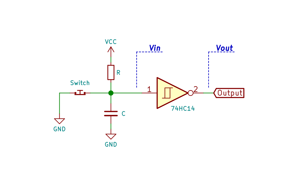 |
| Simple Schmitt trigger debouncer |
TI document SCEA094 presents very briefly this debouncer together with possible combinations of R and C values for certain time constants. This time constant is a parameter of the debouncer circuit that must be adapted to the bouncing time of the switch, which is determined by the physical characteristics of it.
To analyze the $\class{inlineFormula}{\rm{V_{in}}}$ voltage we must consider two states of the switch: open and closed. Remember that in any transition of the switch it bounces from one state to another a few times in a given time.
When the switch is opened the capacitor C charges from $\class{inlineFormula}{\rm{V_{cc}}}$ trough the resistor R.
Assuming that initially the capacitor C is fully discharged and by naming $\class{inlineFormula}{\rm{I_R}}$ the current through the resistor R, $\class{inlineFormula}{\rm{I_C}}$ the current through the capacitor C, and $\class{inlineFormula}{\rm{I_{ST}}}$ the leakage current at the input of the Schmitt trigger then $\class{inlineFormula}{\rm{ I_R = I_C + I_{ST}}}$.
If $\class{inlineFormula}{\rm{ I_{ST} \ll \{I_C, I_R\}}}$ then:
$$ \class{formula}{\rm{ I_R \simeq I_C }} \qquad (1) $$Using Laplace transform, the currents $\class{inlineFormula}{\rm{I_R}}$ and $\class{inlineFormula}{\rm{I_C}}$ can be expressed as:
$$ \class{formula}{\rm{ I_R = \frac{ \left( \frac{V_{CC}-V_{in}}{s} \right)}{R} }} $$ $$ \class{formula}{\rm{ I_C = \frac{V_{in}}{\left( \frac{1}{Cs} \right)} }} $$Substituting $\class{inlineFormula}{\rm{I_R}}$ and $\class{inlineFormula}{\rm{I_C}}$ in (1) gives:
$$ \class{formula}{\rm{ \frac{ \left( \frac{V_{CC}}{s} - V_{in} \right) }{R} = \frac{ V_{in} }{ \left( \frac{1}{Cs} \right) } }} $$From the previous equation is easy to find that:
$$\class{formula}{\rm{ V_{in} = V_{CC} \cdot \frac{ \left( \frac{1}{RC} \right)}{s \cdot \left( \frac{1}{RC} + s \right)} }} $$Now we can use the the inverse Laplace transform:
$$ \class{formula}{\rm{ \mathscr{L^{-1}}\rm{ \left\{ \frac{\alpha}{s \cdot (s+\alpha)} \right\} = \left( 1-e^{-\large{\alpha \cdot t} } \right)} }} $$The voltage at the Schmitt trigger input $\class{inlineFormula}{\rm{V_{in}}}$ is:
$$ \class{formula}{\rm{ V_{in}(t) = V_{CC} \cdot \left( 1- e^{-\large{\frac{t}{RC}} } \right) }} $$When the switch is closed the voltage $\class{inlineFormula}{\rm{V_{in}}}$ drops almost instantly to GND, since the capacitor is discharged through the switch which has almost zero resistance.

|
We can see that this debouncer only debounces the switch signal when it goes from the closed to open state. |
Before continuing, it is worth taking a look at Würth Elektronik support note SN015a as it explains some debouncing circuits in more detail.
A software approach can also be used for this problem. In this case the software, after detecting a switch transition, either by polling or an interrupt, waits a certain time to avoid a false trip on the same switch transition. The two solutions are not mutually exclusive, and a combination of hardware and software debouncing could, and maybe should, be used.
Briot Schmitt Trigger Debouncer
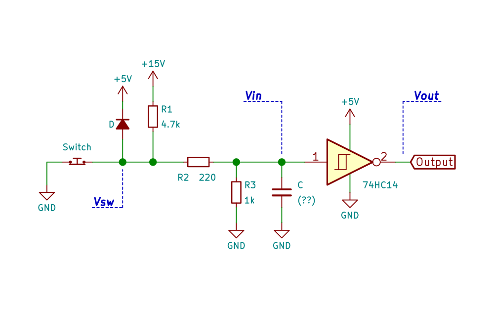 |
| Briot Tracer, Schmitt trigger debouncer circuit schematic |
The debouncer used in the Briot Tracer is different from the classic version of a debouncer. The most significant difference is that it uses the 15V power supply. This introduces two potential problems that need to be addressed:
- The resistors (R1 to R3) must be selected so that $\class{inlineFormula}{\rm{V_{in}}}$ does not exceed 5V, otherwise the Schmitt trigger could be damaged. (Another option is to limit the current at the Schmitt trigger input to less than 20mA, assuming $\class{inlineFormula}{\rm{V_{in}}}$ is set to 5.5V. See Table 4 of the 74HC14 datasheet).
- Since the debouncer is powered from 15V, some sort of overvoltage protection must be built in. If for some reason the voltage $\class{inlineFormula}{\rm{V_{sw}}}$ exceeds $\class{inlineFormula}{\rm{5V+V_D}}$ (where $\class{inlineFormula}{\rm{V_D}}$ is the voltage drop across the diode), diode D1 turns on and clamps the voltage preventing the overvoltage from propagating to the input of the Schmitt trigger through R2.
To eliminate bouncing on both switch transitions (unlike the example shown at the beginning) this circuit adds two resistors. Thus, charging and discharging of the capacitor is done through different resistors, so that both time constants can be controlled independently.
As in the classical Schmitt debouncer, to analyze the $\class{inlineFormula}{\rm{V_{in}}}$ voltage we have to consider two transitions in the circuit: the opening and closing of the switch. During this analysis a couple of assumptions will be made: we assume normal operation, where D1 is always off, and we assume that the leakage current at the input of the Schmitt trigger is negligible compared to other currents.
Opening the switch
When the switch is opened, capacitor C is charged through the voltage divider formed by resistors R1 to R3.
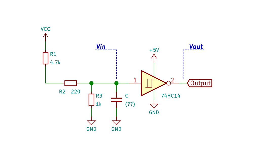 |
| Briot Tracer, Schmitt trigger debouncer equivalent circuit when the switch is open |
Assuming that initially capacitor C is charged at $\class{inlineFormula}{\rm{V_{C0}}}$, and by naming $\class{inlineFormula}{\rm{I_{R1,R2}}}$ the current trough resisotrs R1 and R2, $\class{inlineFormula}{\rm{I_{R3}}}$ the current through the resistors R3 and $\class{inlineFormula}{\rm{I_C}}$ the current through the capacitor C then:
$$\class{formula}{ \rm{ I_{R1,R2} = I_{R3} + I_C }} \qquad (1) $$Using Laplace transform, the currents $\class{inlineFormula}{\rm{I_{R1,R2}}}$ and $\class{inlineFormula}{\rm{I_{R3}}}$ can be expressed as:
$$\class{formula}{ \rm{ I_{R1,R2} = \frac{\left( \frac{V_{CC}}{s} - V_{in} \right)}{R_1 + R2} }}$$ $$\class{formula}{ \rm{ I_{R3} = \frac{V_{in}}{R_3} }}$$ $$\class{formula}{ \rm{ I_C = \frac{\left( V_{in} -\frac{V_{CC}}{s} \right)}{\left( \frac{1}{Cs} \right)} }}$$Substituting the expresion for these currents in (1) gives:
$$\class{formula}{\rm{ \frac{\left( \frac{V_{CC}}{s} - V_{in} \right)}{R_1 + R_2} = \frac{V_{in}}{R_3} + \frac{\left( V_{in} -\frac{V_{CC}}{s} \right)}{\left( \frac{1}{Cs} \right)} }}$$It is easy to find that:
$$\class{formula}{\rm{ V_{in} = \frac{ V_{CC} \cdot R_3}{R_1+R_2+R_3} \cdot \frac{\left( \frac{R_1+R_2+R_3}{(R_1+R_2)R_3C} \right)}{s \left( \frac{R_1+R_2+R_3}{(R_1+R_2)R_3C} + s \right)} + \frac{ V_{C0}}{\left( \frac{R_1+R_2+R_3}{(R_1+R_2)R_3C} + s \right)} }}$$Now we can use the inverse Laplace transforms:
$$ \class{formula}{\rm{ \mathscr{L^{-1}}\rm{ \left\{ \frac{\alpha}{s \cdot (s+\alpha)} \right\} = \left( 1-e^{-\large{\alpha \cdot t} } \right)} }} $$ $$ \class{formula}{\rm{ \mathscr{L^{-1}}\rm{ \left\{ \frac{1}{s+\alpha} \right\} = e^{-\large{\alpha \cdot t} } } }} $$The voltage at the Schmitt trigger input $\class{inlineFormula}{\rm{V_{in}}}$ is:
$$\class{formula}{\rm{ V_{in}(t) = \frac{V_{CC} \cdot R_3}{R_1+R_2+R_3} \cdot \left( 1- e^{-\large{\frac{t}{R_a \cdot C}}} \right) + V_{C0}\cdot e^{-\large{\frac{t}{R_a \cdot C}}} }}$$Where:
$$\class{formula}{ \rm{ R_a = \frac{(R_1+R_2) \cdot R_3}{R_1+R_2+R_3} }}$$And $\class{inlineFormula}{\rm{V_{C0}}}$ is the initial voltage of the capacitor.

|
Substituting with the know values we obtain: $$ \class{formula}{\rm{ V_{in}(t) = 2.53 \cdot \left( 1- e^{-\large{\frac{t}{831.1 \cdot C}} } \right) + V_{C0} \cdot e^{-\large{\frac{t}{831.1 \cdot C}} } }} $$ |
From this formula we can calculate the value at which the capacitor C will remain when $\class{inlineFormula}{\rm{t \to \infty}}$. It is easy to see that this value is $\class{inlineFormula}{\rm{V_{in}(t \to \infty)=2.53V}}$.
Closing the switch
When the switch is closed, capacitor C is discharged through the resistors R2 and R3 (in parallel).
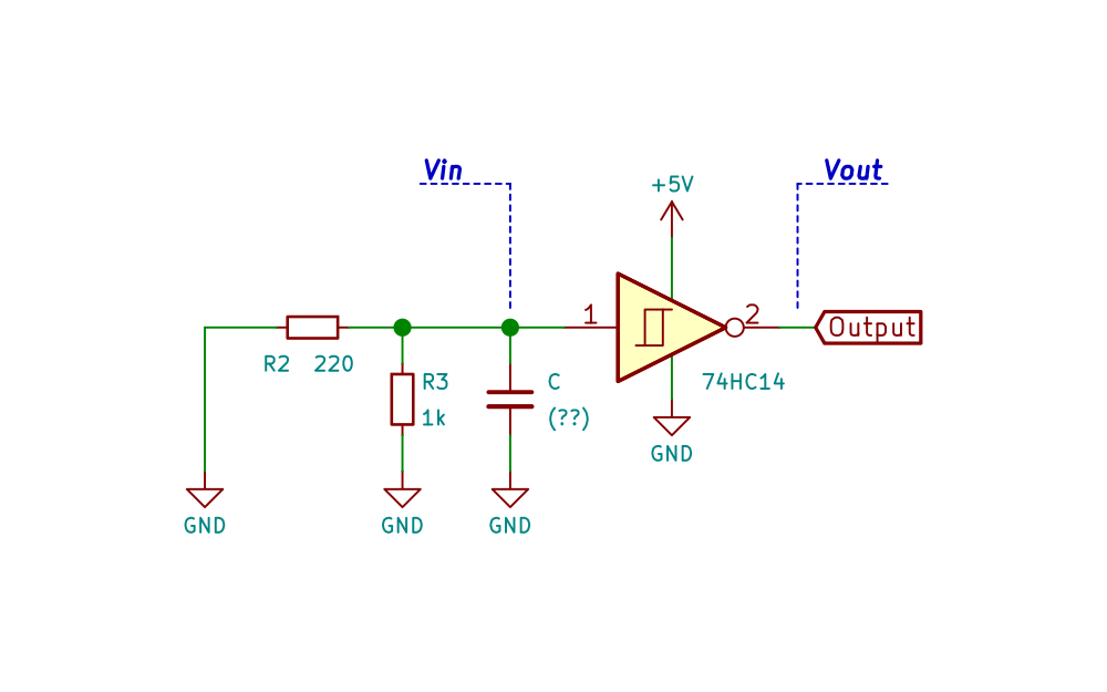 |
| Briot Schmitt trigger debouncer equivalent circuit when the switch is closed |
Assuming that initially the capacitor C is charged at $\class{inlineFormula}{\rm{V_{C0}}}$ and by naming $\class{inlineFormula}{\rm{I_{R2}}}$ and $\class{inlineFormula}{\rm{I_{R3}}}$ the current through the resistors R2 and R3 respectively, and $\class{inlineFormula}{\rm{I_C}}$ the current through the capacitor C then:
$$\class{formula}{ \rm{ I_{R2} + I_{R3} = I_C }} \qquad (1) $$Using Laplace transform, the currents $\class{inlineFormula}{\rm{I_{R2}}}$, $\class{inlineFormula}{\rm{I_{R3}}}$ and $\class{inlineFormula}{\rm{I_C}}$ can be expressed as:
$$\class{formula}{ \rm{ I_{R2} = \frac{V_{in}}{R_2} }}$$ $$\class{formula}{ \rm{ I_{R3} = \frac{V_{in}}{R_3} }}$$ $$\class{formula}{ \rm{ I_C = \frac{\left( \frac{V_{C0}}{s} - V_{in} \right)}{\left( \frac{1}{Cs}\right)} }}$$Substituting in (1) gives:
$$\class{formula}{ \rm{ \frac{V_{in}}{R_2} + \frac{V_{in}}{R_3} = \frac{ \left( \frac{V_{C0}}{s}-V_{in} \right)}{ \left(\frac{1}{Cs}\right) } }}$$It is easy to find that:
$$\class{formula}{\rm{ V_{in} = \frac{V_{C0}}{\left( \frac{R_2+R_3}{R_2R_3C} + s \right) } }}$$Now we can use the inverse Laplace transform:
$$ \class{formula}{\rm{ \mathscr{L^{-1}}\rm{ \left\{ \frac{1}{s+\alpha} \right\} = e^{-\large{\alpha \cdot t} } } }} $$The voltage at the Schmitt trigger input $\class{inlineFormula}{\rm{V_{in}}}$ is in this case:
$$ \class{formula}{\rm{ V_{in}(t) = V_{C0} \cdot e^{-\large{\frac{t}{R_b \cdot C}}} }} $$Where:
$$ \class{formula}{\rm{ R_b = \frac{R_2 \cdot R_3}{R_2+R_3} }} $$

|
Substituting we obtain: $$ \class{formula}{\rm{ V_{in}(t) = 2.53 \cdot e^{-\large{\frac{t}{180.3 \cdot C}} } }} $$ |
From this formula we can calculate the value at which the capacitor C will remain when $\class{inlineFormula}{\rm{t \to \infty}}$. It is easy to see that this value is $\class{inlineFormula}{\rm{V_{in}(t \to \infty)=0V}}$.
How do we deduce the value of C?
I did not measure the value of capacitor C during the reverse engineering of the circuit since it had to be desoldered to measure its value. But I happened to have a photo of the input and output signals of one of the Schmitt triggers which I took during the repair. Using that photo we can deduce the value of C. It is really not that hard if we know what we are looking for and what information is in that photo.
 |
| Oscilloscope capture when the switch closes. [Yellow: $\class{inlineFormula}{\rm{V_{in}}}$, Cian: $\class{inlineFormula}{\rm{V_{out}}}$] |
Also I have a photo of the same signals when the switch opens. By observing the signals it can be seen that the behavior is quite different, if we compare the amount of bounces when the switch is opened and when the switch is closed.
This behavior is not an isolated situation, I made several captures of both transitions with the oscilloscope, and what is shown in the images could be said to be representative of the response in both cases. This difference, in terms of the amount of bounce, is not related to the electronic circuit, and I think it could be related to the physical characteristics of the switch itself, but this is just a guess.
 |
| Oscilloscope capture when the switch opens. [Yellow: $\class{inlineFormula}{\rm{V_{in}}}$, Cian: $\class{inlineFormula}{\rm{V_{out}}}$] |
As we have the formula for $\class{inlineFormula}{\rm{V_{in}}}$ when the switch is opened:
$$\class{formula}{\rm{ V_{in}(t) = 2.53 \cdot \left( 1- e^{-\large{\frac{t}{831.1 \cdot C}}} \right) + V_{C0}\cdot e^{-\large{\frac{t}{831.1 \cdot C}}} }}$$As the capacitor is initialy discharged, it means that $\class{inlineFormula}{\rm{V_{C0}=0}}$, we have:
$$ \class{formula}{\rm{ V_{in}(t) = 2.53 \cdot \left( 1- e^{-\large{\frac{t}{831.1 \cdot C}} } \right) }} $$We can plot $\class{inlineFormula}{\rm{V_{in}}}$ for some common values of C and compare each curve with the $\class{inlineFormula}{\rm{V_{in}}}$ plot obtained with the oscilloscope, the one that matches corresponds to the correct value of C.
 |
| Plot of $\class{inlineFormula}{\rm{V_{in}}}$ for some values of C |
We can now superimpose these two images. The scale of the graph was adjusted to match the horizontal (time base) and the vertical scale of the oscilloscope CH1 used during capture, $\class{inlineFormula}{\rm{200\mu s/div}}$ and $\class{inlineFormula}{\rm{1 V/div}}$ respectively.
 |
| $\class{inlineFormula}{\rm{V_{in}}}$ for various C values |
It appears that the value of the capacitor is 47nF, and we can now substitute this value into the equation of $\class{inlineFormula}{\rm{V_{in}}}$ for the opening and closing of the switch.

|
Switch opening: $$ \class{formula}{\rm{ V_{in}(t) = 2.53 \cdot \left( 1- e^{-\large{\frac{t}{39.1x10^{-6}}} } \right) + V_{C0}\cdot e^{-\large{\frac{t}{39.1x10^{-6}}}} }} $$ |
|
|
Switch closing: $$ \class{formula}{\rm{ V_{in}(t) = V_{C0} \cdot e^{-\large{\frac{t}{8.47x10^{-6}}} } }} $$ |
 |
Writing a program in Octave to simulate the behavior of this circuit I found a problem with the schematic. The Schmitt trigger inverter used in the Briot tracer is not an 74HC14 but an 74HCT14. This error was corrected in revision 1.1 (hierarchical) and 1.3 (non-hierarchical) and updated in the corresponding entries in this blog. Can you figure out how/why I found this error?. Hint: Look at the differences in the 74HC/HCT14 datasheet (Page 7: $\class{inlineFormula}{\rm{V_{T+}}}$) and consider the final value ($\class{inlineFormula}{\rm{t \to \infty}}$) of $\class{inlineFormula}{\rm{V_{in}}}$ when the switch is opened. |
Octave Simulation
To simulate the behavior of this circuit you can use SPICE. But in this simple case I prefer to exercise a little with Octave programming since I have not used it for some time. I am not going to explain the program in detail, I think it is self-explanatory and well commented, but I will show what it can do.
The program consists of three files: one that implements a general representation of the capacitor charge/discharge function (charge_discharge_formula.m), one that stores the parameters for these functions (params.m), and finally a function that executes the simulation (sim_debouncer.m).
The parameters stored in the params.m file used for this simulation, correspond to the values calculated for the Briot Tracer debouncer.
As an example, the following images show the two graphs produced by the simulation, for which the parameters used were:
- deltaT: $\class{inlineFormula}{\rm{1 \mu s}}$
- duration: $\class{inlineFormula}{\rm{2.5 m s}}$
- min_stable_time: $\class{inlineFormula}{\rm{100 \mu s}}$
- pre_after_time: $\class{inlineFormula}{\rm{500 \mu s}}$
- initial_state: $\class{inlineFormula}{\rm{1}}$
- neg_trigger: $\class{inlineFormula}{\rm{0.75}}$
- pos_trigger: $\class{inlineFormula}{\rm{1.9}}$
- vcc: $\class{inlineFormula}{\rm{5}}$
The first figure produced by the program includes the three traces in the same graph, to allow a better view of the temporal correlation of each signal.
 |
| Switch Debouncer Simulation, Figure 1 |
The second figure creates a graph for each plot independently, to allow a better view of each one of them.
 |
| Switch Debouncer Simulation, Figure 2 |
To call the program with these parameters execute the following in the Octave console: $\class{inlineFormula}{\rm{\verb|sim_debouncer(1e-6, 2.5e-3, 100e-6, 500e-6, 1, 0.75, 1.9, 5);|}}$

|
Download the ZIP file containing the three .m files required for the Octave simulation. |
I hope you find this information useful.
No comments:
Post a Comment