Some time ago I was asked to take a look to a machine from an optical laboratory with a non trivial type of fault to solve: an intermittent fault in a machine with moving parts. It is a thermal problem? It is a unstable solder? It is a bad cable?
I will show the problem encountered and how I'd solved it. In future entries I will share more information reverse engineering about the Briot Tracer, stay nearby.
Machine Description
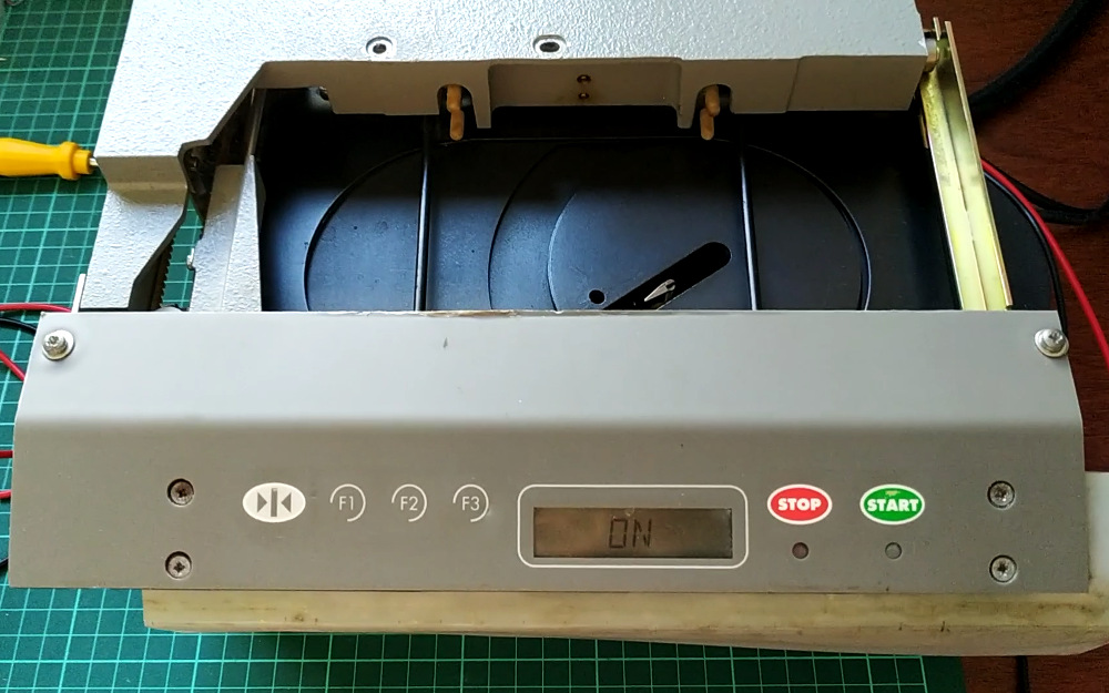
The machine is an Accura CX BW as was reported by the owner and the problem was the Tracer or Scanner, whose function is to scan the glasses frame and produce some sort of 3D data that is then used to cut each glass to match the frame shape.
 |
| Briot Tracer main PCB |
It is very helpfull that the scanner can be tested without being connected to the main machine. Just apply 24V (AC or DC as it has a full wave rectifier) on connector J6 and it will turn on.
When the tracer is turned on it performs some sort of initialization/calibration/test process. This ensures that everything works as intended and the tracer is always in a know position when it finishes this process and before starting a frame scan process.
| Briot Tracer - Normal initialization process |
Sorry for the quality of the video, it was recorded just to be sent to the owner after the repair.
The scanning mechanism is based on a carriage that is capable of moving a scanning tip in the space above it, as can be seen in the previous video. The scanning mechanism have 4 "degrees" of movement:
- Translation: The carriage moves left and right.
- Rotation: The rotating head rotates over itself.
- Rho: The sensing tip moves radially with respect to the center of rotation.
- Z: The sensing tip moves up and down.
Fault(s) description
The scanner actually presented two faults:
- Fault 1: Sometimes during the rotation movement the tracer shuts down. In this fault the led LD2 (15V) stays on, while the led LD1 (5V) turns off and the led D37 (CPU ACTIVITY) stops blinking.
- Fault 2: Sometimes the initialization process is completed. When it is not, it always stop with the sensing tip pointing to the front of the scanner (where the display is) and shows ER02 in the display.
Solving Fault 1 (Intermittent rotation fault)
As the symptom of this fault seems to indicate a short circuit in the 5V power supply it makes sense (to avoid more damage) to use a power supply with current limiting capabilities for further testing.
The first step is to understand the power supply and voltage regulation circuit. The scanner is powered through a connector (J6) located on the lower left side of the PCB, by a 24VAC power supply. Starting from that connector I reverse engineered the power supply circuit.
 |
| Briot Tracer power supply circuit schematic |
During the tests the scanner was powered (by a Rigol DP832 power supply) with 24VDC limiting the current to 400mA. I was able to confirm (due to the activation of the current limit) that the scanner doesn't actually shut down but causes a short circuit during the rotating. This was also confirmed by a thermal showing an increase in temperature of the zener diodes D47 and D48 and the voltage regulator U11. During the short circuit the zener diodes reached temperatures above 140°C until I shutted down the power supply as a precaution.
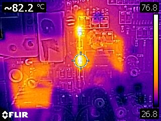 |
| Normal working temperature of the zener diodes |

|
From the zener datasheet -BZX85C3V3- the maximum power disipation is: $\class{inlineFormula}{\rm{P^{max}_D=1,0W}}$ at $\class{inlineFormula}{\rm{T_A=25°C}}$ which for a 3.3V zener means a maximum current of 303mA. The power supply reports a current of 280mA doing nothing, wich is just under the 303mA limit. In fact the margin is 7.6% wich is not too much as a safety margin. |
Checking the position of the rotating head while the short circuit was in place, I can see that the flat cable that goes from the main board trough the center of the rotating head is fully twisted. As a result, every time the head rotates the cable rubs against the edge of a piece of metal that serves as a guide for the cable.
In the center of the following image you can see the white connector where the flat cable is connected. Behind it is a metal guide that ensures that the flat cable does not lift during rotation.
 |
| Briot Tracer rotation head (flat cable connector and rotation switches) |
Looking carefully I can see that the protective cover of the flat cable was scratched exposing the metal conductor. Since the metal structure of the scanner is grounded and the exposed conductor is actually the 5V power supply, we found the source of the short circuit.
This cable was replaced by a technician some time ago. He did not do a good job, the way the cable was installed is clearly the reason for the fault.
Replacing the cable solved the first fault, one solved, one more to go. As a precaution and since the owner had some on hand, both zener diodes were replaced with new ones.

|
The cable was installed so that it rotates half in each direction, and a little tight to avoid scratching against the metal cable guide. A couple of months later, the latter proved to be a bad idea, the cable broke again. The entire rotation head was dissembled -something that I was trying to avoid- and the metal cable guide was filed down to smooth the sharp borders. The cable was replaced again and installed in a more relaxed way. |
Solving Fault 2 (Error ER02 during initialization)
The second fault happens during the rotation movement, in the counterclockwise direction.
To control the rotation movement the scanner has a series of switches. One switch detects the clockwise rotation end, and two more switches detects the counterclockwise rotation end. The fault happens when the second counterclockwise switch is reached, so this switch signal must be traced down and analyzed.
Both switches are connected to an intermediate PCB located under the rotating head. From there a flat cable connects them (and other signals) to the connector J5 in the main PCB. (In the the lower left side of the Rotation Head image you can see the counterclockwise rotation end switches).
 |
| Briot Tracer undercarriage intermediate PCB (stepper and rotation swithces) |
Before removing the intermediate PCB, the switch signals were traced back to the main PCB and, again, the circuit was reverse-engineered around these signals. The switches of interest are connected to the signals named Rot_Sw_CW1 and Rot_Sw_CW2.
 |
| Briot Tracer, rotation switches debouncer circuit schematic |
This is not a classic Schmitt trigger debouncer. I will analyze this circuit in a future post.
The output of the Schmitt triggers is checked with an oscilloscope (Rigol DS1054Z) while manually activating each switch and both are working correctly. The problem is somewhere else. As the fault was intermittent that intermediate PCB was removed.
 |
| Briot Tracer undercarriage PCB. Cracked solder joints of rotation switches connector |
It is clear that the failure is caused by cracked solder joints. After repairing the broken solder joints, the scanner started working properly.
 |
| Briot Tracer undercarriage PCB. Almost cracked solder joints of stepper motor connector |
As a preventive measure, all solder joints on this board were re-soldered.
No comments:
Post a Comment