While I was repairing a Briot Tracer, certain sections of the main PCB circuit were reverse engineered. Mostly the power supply and the circuits associated with the debouncers of the rotary switches. Some time later the scanner broke again, this time the fault was not obvious and to try to find the problem it was necessary to reverse engineer other parts of the circuit. While I was waiting for an IC to arrive I took the opportunity to do a complete reverse engineering of the whole system.
In this entry I will share the complete schematic of the Briot Tracer.
The main reason I did this, besides the fact that I needed it to solve a fault, is to help others who have to solve an electronic problem with the tracer.
Let me say that this took a lot of time, about 80 hours to complete the final schematic. One of the reasons is that reverse engineering a circuit with such a large number of components manually is not easy, for each pin of each IC you have to find to which other components it is connected. The other reason is that, to be useful, the Kicad schematic has to be well organized, which also takes time. Not to mention that most of the integrated circuits were not available as part of the Kicad libraries, so they had to be created.
One of the things that can be very useful is to document the test points on the main PCB. It has a lot of them, and I found that most of them correspond to important signals. Unfortunately I ran out of time to add the information to the schematic and mark their position on an image of the PCB as I had to return the tracer to its owner.
Main PCB pictures
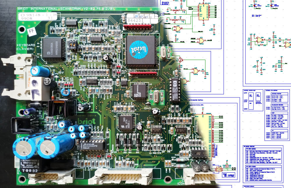
In the following two pictures you can see the main PCB, which has at least four layers. The sticker on the microcontroller states 03-99, that is March 1999, perhaps this is the date of manufacture.
 |
| Briot Tracer Main PCB - Front |
In the upper left part of the above image you can read the model and version of the main PCB: BRIOT INTERNATIONAL-SCANFORM4-V2-02.75.012/01
 |
| Briot Tracer Main PCB - Back |
Nothing special on the back.
Keyboard and Display PCB pictures
In the following two pictures you can see the keyboard and display PCB. Unlike the main board this one could be two-layer, but that cannot be confirmed.
 |
| Briot Tracer keyboard and display PCB - Front |
In the lower right part of the above image you can read what appears to be the version of the PCB: BRIOT INTERNATIONAL 02 75 007-02
 |
| Briot Tracer keyboard and display PCB - Back |
The sticker on the back of this PCB also states 03-99.
Complete Tracer Schematic

|
The schematic may contain some minor errors and may be missing a few passive components. Please take into consideration the size of the circuit and the large amount of components involved before getting upset. Probably 99% of the schematic is correct. |
As previously mentioned, the process for reverse engineering the circuit consisted of choosing an IC and for each of its pins finding which other components it was connected to, documenting in all cases its designation according to the silkscreen, and the value whenever possible. When you are done with that IC you move on to the next one. Common sense and experience are good tools to use during this process, as they help to decide when the circuit is complete for each pin of an IC.
For most components finding the value is easy. The exception is ceramic capacitors for which most of the time the only solution to measure its value is to desolder them.
The complete Kicad schematic does not fit on an A4 size sheet, an A1 page size is required. This is not very convenient if you want to use the schematic in paper format (it is a very large piece of paper: 60cm by 84cm), but it is useful to use it in digital format, for example to quickly find a component in the schematic by its reference.
April 04, 2021: Updated the schematic to revision 1.1
April 05, 2021: Updated the schematic to revision 1.2
April 27, 2021: Updated the schematic to revision 1.3
December 17, 2021: Updated the schematic to revision 1.4
| Briot Tracer Complete PDF Circuit Schematic (Rev. 1.4) - A1 page |

|
Download the Briot tracer complete circuit schematic in PDF (Rev. 1.4) |

|
Download the Kicad project that contains the Briot tracer circuit schematic (Rev. 1.4) |

|
I am creating a hierarchical schematic on several A4 sheets so that it can be printed without difficulties. I will publish it in a future post, stay close. |
No comments:
Post a Comment